Handling & Lifting Solution/A-Frame
Handling support
A-frames and L-frames for overboarding
- Hydraulic A-frames to 60 t SWL — Standard, variable-section, telescopic full-overturn and negative-angle overturn types, inboard/outboard swing up to −70°/+135°.
- Electric frames at 1 t, 5 t and 15 t — No hydraulic power unit or oil piping on deck, higher integration and a cleaner deck layout.
- Closed-loop position and speed control — Smooth start and stop with fast response; ready for remote or automated operation with condition monitoring and fault diagnosis modules.
- Lower maintenance — No hydraulic oil changes or filter servicing on electric frames, with lower noise, heat and standby power.
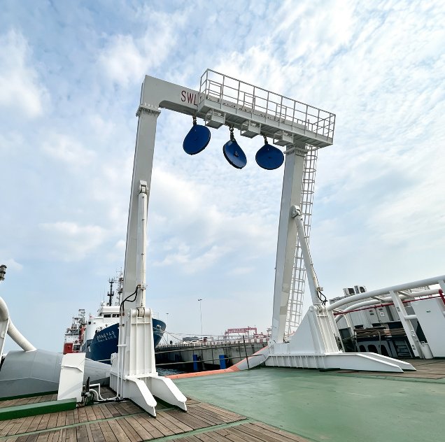
A-Frame
Overview
The Handling Support range covers A-frames, L-frames and telescopic gantries that lift equipment over the stern or side of a vessel and swing it inboard for stowage. They are matched to the winches in the same range and to the ROV, towfish and sampling gear they serve.
Hydraulic heavy-duty A-frames are configured per vessel. Two reference configurations are shown below: a gantry-type frame with 20 t dynamic / 30 t static load on the main sheave and 10 t / 15 t on the auxiliary sheave, and a frame rated 16 t for the inboard swing and 30 t static outboard. Custom variants cover 0–20 t and 0–60 t SWL, with swing ranges from −50°/+60° up to −70°/+135° inboard/outboard, and a hangar-top telescopic gantry with 0–10 m travel.
Electric L-frames and A-frames with 1 t, 5 t and 15 t SWL are available together with electric docking heads. They need no hydraulic power unit or oil piping, give closed-loop control of position and speed, and are simpler to maintain. All frames are designed and supplied by OCEAN PHYSICS.
Specifications
Technical data
| Hydraulic heavy-duty A-frame — reference configurations | ||
|---|---|---|
| Item | Gantry-type A-frame | A-frame 16 t / 30 t |
| Working load | Main sheave: 20 T dynamic / 30 T static; auxiliary sheave: 10 T dynamic / 15 T static | 16 t inboard swing; 30 t static outboard |
| Luffing / swing time | ≤160 s (dual pump set, 6 m outboard to 4.5 m inboard); ≤280 s (single pump set) | approx. 150 s (inboard to outboard) |
| Outreach / inreach | Outboard ≥6 m; inboard ≥4.5 m (from base outer edge to lifting point) | Outreach approx. 7500 mm; inreach approx. 12500 mm |
| Height | ≥10 m from main lifting point to deck (frame vertical) | Net height approx. 10795 mm (from sheave bottom); maintenance position approx. 1480 mm |
| Width | ≥6.5 m between columns | Net width approx. 7500 mm; overall width approx. 9700 mm |
| Wire rope at sheaves | Main 20 T block: approx. Φ21 mm; auxiliary 10 T block: approx. Φ17.3 mm | — |
| Drive | Hydraulic | Hydraulic |
| Power supply | — | — |
| Weight | — | — |
| Material | — | — |
| Control | — | — |
| Platform / mounting | — | — |
| Frame types available | ||
| Type | SWL | Swing (inboard / outboard) |
| Hydraulic A-frame | 0–20 t | −50° / +60° |
| Hydraulic A-frame, variable-section beam | 0–20 t | −50° / +60° |
| Hydraulic telescopic A-frame, full overturn | 0–60 t | −80° / +90° |
| Hydraulic A-frame, negative-angle overturn | 0–60 t | −70° / +135° |
| Hydraulic L-frame | 0–20 t | −50° / +60° |
| Electric L-frame | 0–20 t | −50° / +60° |
| Electric L-frame, full overturn | 0–20 t | −50° / +90° |
| Hangar-top telescopic gantry | 0–20 t | Travel 0–10 m; outboard tilt 0–90° |
| Electric L-frame / A-frame (standard sizes) | 1 t · 5 t · 15 t | — |
| Additional details — 16 t inboard / 30 t static outboard reference configuration | ||
| Frame material (16 t / 30 t configuration) | Steel structure | |
| Control (16 t / 30 t configuration) | Hydraulic control | |
| Mounting (16 t / 30 t configuration) | Stern installation on research or engineering vessels | |
Discuss Handling support for your project
Tell us about your vessel, water depth and deliverables, and our engineers will recommend a configuration.